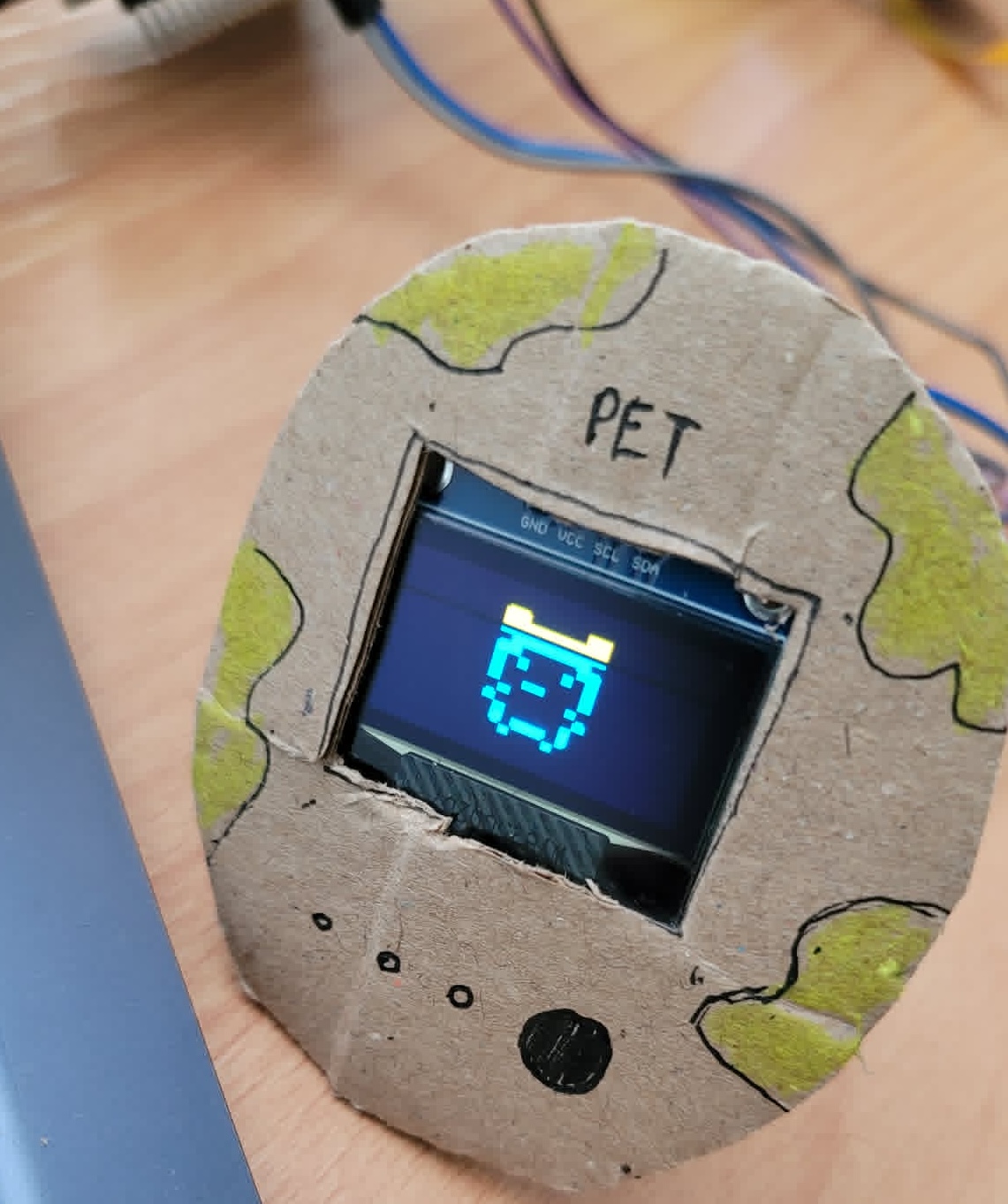
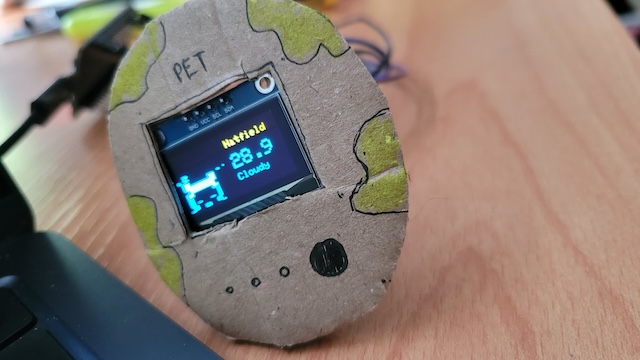
Build a tamagotchi (pet) with ESP32 and OLED display
Published at May 27, 2026
I heard analog is back in 2026.
I heard it’s a deliberate rebellion against digital fatigue.
As someone who loves indulging in nostalgia, I’m riding this wave, but in a slightly different way.
My day job is software engineer, so I’m working with tech and AI every day. I wanted my AI agent to extend its presence into a physical body — something on my desk that shows me it’s “alive” and working, like a pet.
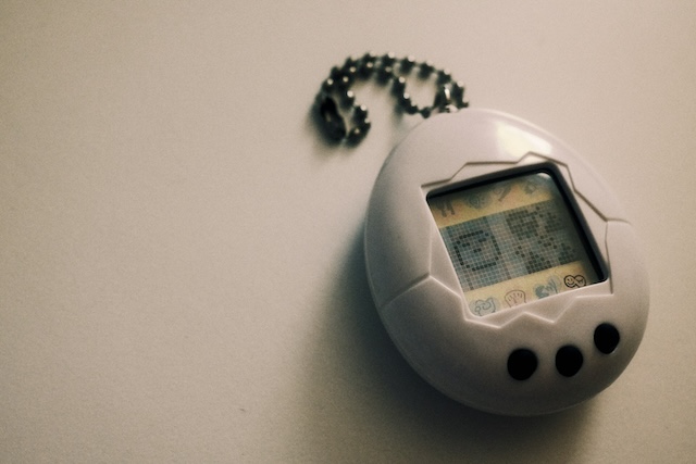
Tamagotchi was my favourite childhood toy. Why not combine the old with the new, software with hardware? That’s the idea.
What you’ll need
Hardware
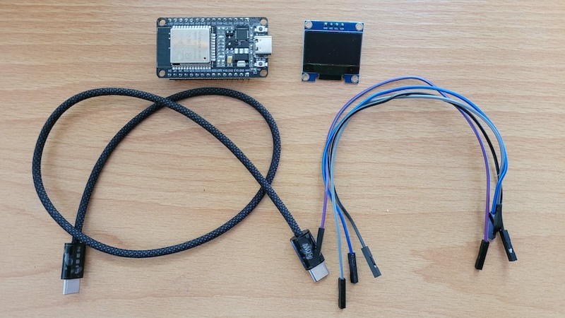
- 1 ESP32 board (any variant works. I got mine from Amazon but you can also buy it from Shopee)
- SSD1306 OLED display (128x64, I2C)
- 4 jumper wires
- USB cable (mine is type C to connect with Macbook)
Software
Step 1: Install Arduino IDE
- Go to arduino.cc/en/software
- Download the version for your OS (macOS, Windows, or Linux)
- Open Arduino IDE and let it install any default components it asks for
Step 2: Connect ESP32 to your Mac (computer)
I plug ESP32 into my MacBook via USB for both power and code uploading.
Open Arduino IDE and:
- Go to Tools → Board → Boards Manager, search “esp32”, and install esp32 by Espressif Systems
- Go to Tools → Board and select your ESP32 variant (e.g. “ESP32 Dev Module”)
- Go to Tools → Port and select the port that appeared (usually
/dev/cu.usbserial-*or/dev/cu.SLAB_USBtoUART)
Step 3: Wire the OLED display
You see how these pins are labeled: VCC, SCL, etc.
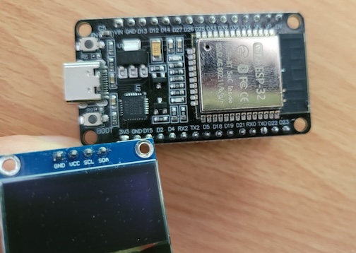
Let’s connect OLED pins to ESP32 pins!
| OLED Pin | ESP32 Pin |
|---|---|
| VCC | 3.3V |
| GND | GND |
| SDA | GPIO 21 or D21 |
| SCL | GPIO 22 or D22 |
Step 4: Install libraries and test our first text display
In Arduino IDE, go to Sketch → Include Library → Manage Libraries and install:
- Adafruit GFX Library
- Adafruit SSD1306
Now paste this test code (you can also ask Claude or ChatGPT to write code example for testing), click upload to confirm everything works:
// use libraries
#include <Wire.h>
#include <Adafruit_GFX.h>
#include <Adafruit_SSD1306.h>

Adafruit_SSD1306 display(128, 64, &Wire, -1);

void setup() {
  Wire.begin(21, 22); //tells ESP32 which pins for communication
  display.begin(SSD1306_SWITCHCAPVCC, 0x3C);
  display.clearDisplay();
  display.setTextSize(2);
  display.setTextColor(WHITE); // default is no color
  display.setCursor(10, 20); //position text
  display.println("Hello Thuyet!"); //or whatever
  display.display();
}

void loop() {}
If you see “Hello Thuyet!” on the OLED, your wiring and setup are good. If not, double-check:
- SDA is on GPIO 21, SCL is on GPIO 22
- The OLED I2C address is
0x3C(some displays use0x3D) - The display is getting 3.3V power
Step 5: The logic — WiFi + HTTP API
Now for the real thing. The ESP32 runs a web server with these endpoints:
POST /active— wakes the pet up (agent is working)POST /idle— puts the pet to sleep (agent stopped)GET /status— returns current state
The device is discoverable via mDNS at http://pet.local, so your agent doesn’t
need to know the IP address.
There’s also an auto-sleep timeout: if no /active request comes in for 30
seconds, the pet goes to sleep on its own.
The full sketch uses these additional built-in ESP32 libraries (no install needed):
- WiFi
- WebServer
- ESPmDNS
Then upload this code:
#include <Wire.h>
#include <Adafruit_GFX.h>
#include <Adafruit_SSD1306.h>
#include <WiFi.h>
#include <WebServer.h>
#include <ESPmDNS.h>

Adafruit_SSD1306 display(128, 64, &Wire, -1);

const char* ssid = "YOUR_WIFI_SSID";
const char* password = "YOUR_WIFI_PASSWORD";
const char* hostname = "pet";

WebServer server(80);
The key parts of the logic:
int emotion = 1; // Start sleeping
unsigned long lastActiveTime = 0;
const unsigned long autoSleepTimeout = 30000; // 30s

void handleActive() {
  emotion = 0;
  lastActiveTime = millis();
  server.send(200, "text/plain", "ok");
}

void handleIdle() {
  emotion = 1;
  server.send(200, "text/plain", "ok");
}

void handleStatus() {
  server.send(200, "text/plain", emotion == 0 ? "active" : "idle");
}
In setup(), connect to WiFi, start mDNS, and register the routes:
void setup() {
  Serial.begin(115200); // lets us print debug messages. 115200 is the speed of communication over USB serial
  Wire.begin(21, 22);
  display.begin(SSD1306_SWITCHCAPVCC, 0x3C);

  WiFi.begin(ssid, password);
  while (WiFi.status() != WL_CONNECTED) {
    delay(500);
  }

  MDNS.begin(hostname); // http://pet.local

  server.on("/active", HTTP_POST, handleActive);
  server.on("/idle", HTTP_POST, handleIdle);
  server.on("/status", HTTP_GET, handleStatus);
  server.begin();
}
In loop(), handle requests, check for auto-sleep, and draw the current emotion
bitmap:
void loop() {
  server.handleClient();

  // Auto-sleep after 30s of no activity
  if (emotion == 0 && (millis() - lastActiveTime > autoSleepTimeout)) {
    emotion = 1;
  }

  display.clearDisplay();
  if (emotion == 0) {
    display.drawBitmap(40, 8, normal_bitmap, 48, 48, WHITE);
  } else {
    display.drawBitmap(40, 8, sleep_bitmap, 60, 52, WHITE);
  }
  display.display();
  delay(30);
}
For the bitmap data (the pixel art faces), I used image2cpp to convert small PNG drawings into C arrays.
Bitmap data: turning pixel art into code

The OLED can’t display image files directly. Instead, you give it a C array of bytes where each bit represents a pixel (1 = white, 0 = black).
To create your own:
- Draw a small image (48x48px works well) in any editor, or find pixel art online
- Save it as a monochrome PNG (black and white only)
- Go to image2cpp
- Upload your image, set the canvas size to match, and select “Arduino code” as output
- Copy the generated array into your sketch
The output looks something like this:
const unsigned char normal_bitmap[] PROGMEM = {
  0x00, 0x00, 0x00, 0x00, 0x00, 0x00,
  0x00, 0x07, 0xf0, 0x0f, 0xe0, 0x00,
  0x00, 0x1f, 0xfc, 0x3f, 0xf8, 0x00,
  // ... more rows
};
Each row of hex values maps to a row of pixels on screen. PROGMEM stores it in
flash memory instead of RAM (important since ESP32 RAM is limited).
Then use it with:
display.drawBitmap(x, y, normal_bitmap, width, height, WHITE);Where x, y is the top-left position, and width, height match your image
dimensions.
Step 6: Connect your AI agent
The ESP32 web server is running. Now you need your AI agent to actually hit it.
The idea: when the agent starts working, it sends POST /active. When it stops,
it sends POST /idle.
Test manually with curl first:
curl -X POST http://pet.local/active   # wake
curl -X POST http://pet.local/idle     # sleep
curl http://pet.local/status           # check state
Setting up hooks in Kiro
Kiro or Claude has agent hooks that fire commands on IDE events. You can ask
them to create hooks for you. Otherwise, create two JSON files in ~/.kiro/hooks/ (user-level, so they work across all your projects):
~/.kiro/hooks/wake-esp32-pet.json
{
  "name": "Wake ESP32 Pet",
  "version": "1.0.0",
  "when": {
    "type": "promptSubmit"
  },
  "then": {
    "type": "runCommand",
    "command": "curl -s -X POST http://pet.local/active"
  }
}
~/.kiro/hooks/sleep-esp32-pet.json
{
  "name": "Sleep ESP32 Pet",
  "version": "1.0.0",
  "when": {
    "type": "agentStop"
  },
  "then": {
    "type": "runCommand",
    "command": "curl -s -X POST http://pet.local/idle"
  }
}
Placing hooks in ~/.kiro/hooks/ makes them global. If you put them in a
project’s .kiro/hooks/ folder instead, they only work in that workspace.
Now every time you send a message to the agent, the pet wakes up. When the agent finishes, it goes back to sleep. The 30-second auto-sleep timeout acts as a safety net if the agent crashes without triggering the stop hook.
Next steps
- Add more emotions (thinking, error, happy)
- Use WebSocket instead of polling for real-time state
- Add a small speaker for sound feedback
- Display weather, screen time, or reminders